Chevy 216 and 235 Firing Order and Timing Marks
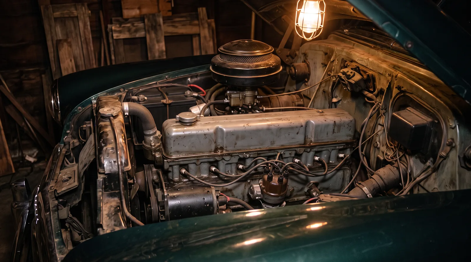
The chevy 235 firing order is 1-5-3-6-2-4, and so is the 216's. That is the short answer, and it is printed in the 1951 owner's manual for both engines. The longer answer is where people get into trouble: which cylinder is No. 1, which way the rotor turns, and where on earth the timing mark is, because on a 1951 it is not where a later Chevrolet has trained you to look. I have watched more than one owner stand at the front of the engine with a timing light, hunting for a tab on the balancer that was never there. If you are not sure which of the 216 and the 235 you have, settle that first, then come back with a light and a wrench.
The chevy 235 firing order and cylinder numbering
Every factory source I trust for these years says the same thing: 1-5-3-6-2-4. The 1949 car manual gives it for the 216, the 1948 to 1951 truck manual gives it for both the 216 and the 235, the 1950 to 1951 supplement uses it for the Powerglide 235, and the 1951 owner's manual lists it for the standard 216 (92 hp) and the Powerglide 235 (105 hp) alike. There is no separate chevy 216 firing order to memorize.
Cylinder No. 1 is the front cylinder, by the water pump, and the count runs back to No. 6. That is how an owner on the VCCA forum puts it, and I have never seen one numbered otherwise, but I could not find the sentence in a factory page, so check it against your own manual.
Distributor position and rotation
The distributor sits on the right side of the engine, gear-driven from the camshaft, so the rotor "turns at camshaft speed." The lower end of the distributor shaft also drives the oil pump. Pull the distributor and the pump drive comes out with it.
Rotor rotation is clockwise, viewed from the top. I give you that with a caution. The 1948 to 1951 truck manual and the 1955 car manual both tell you to check the centrifugal advance by turning the cam clockwise, and the cap diagram in the 1949 manual runs 1-5-3-6-2-4 clockwise. One sentence in the 1949 car manual says counterclockwise, and it is the odd one out. Do what I do: pull the cap, have someone bump the starter, and watch which way the rotor goes. It takes ten seconds and ends the argument.
Owners on the VCCA forum note that the distributor will go in at any position as long as the oil pump is lined up with the end of the distributor shaft, so the No. 1 tower is not fixed by the engine. You point the rotor at whichever tower you call No. 1 and wire the rest clockwise in firing order. Owners quote different clock positions for the No. 1 wire for exactly that reason, so do not go by someone else's cap. If yours is somewhere else and the engine runs right, leave it. For the points, condenser and cap themselves, see the distributor and points.
"Half the timing jobs I get called in on are fine. The man just aimed his light at the pulley. On these engines the mark lives in the flywheel, and it always has."
— Earl Dawson
Where the timing marks are on a 1951 engine
Here is the part that catches people. On the 1951 216 and 235, the timing reference is a steel ball set in the flywheel, seen through an opening in the flywheel housing, lined up against a pointer on the housing. The factory procedure has you hook a timing light to No. 1 plug, run the engine at idle, aim the light at the flywheel housing opening and rotate the distributor until "the steel ball in the flywheel lines up with the pointer on the flywheel housing."
The balancer at the front carries no timing marks in any factory procedure I have read for 1949 to 1955, and the 1955 car manual still uses the ball. If someone has painted a line on your pulley, it is his line, not the factory's. I cannot tell you the year the marks moved to the front of the engine, because I have not found it written down.
Setting basic timing, step by step
Start by finding No. 1 at top center on its compression stroke. The supplement's method needs no light: crank the engine until the rotor points to the No. 1 position with the breaker points open, and No. 1 piston is at top center on compression. One VCCA owner lines up the ball and pointer at that moment and sets the distributor from there. That gets you close enough to start it. The final setting is done with the light, engine running.
Check this first
- Points and plugs. Set the point gap to .018 inch (.022 to .024 inch on new points in the car manual) with 17 to 21 oz spring tension. Plug gap is .035 inch on 14 mm plugs, tightened to 20 to 25 ft-lb.
- Octane selector at "0". These distributors carry an octane selector with a scale. The factory sets timing with it at zero.
- Idle. Bring the engine to 450 to 500 rpm, where the manual expects 17 to 21 inches of vacuum. On the 1950 to 1951 Powerglide 235 the supplement checks idle at 430 to 450 rpm in Park.
- Light on No. 1. Aim it at the flywheel housing opening and turn the distributor body until the ball lines up with the pointer. That is how the manual sets its 5 degrees before top center.
- Road test. The factory then adjusts on the road so the engine gives a slight ping at wide-open throttle, using the octane selector.
The vacuum spark control is a diaphragm on the distributor bracket, connected to the carburetor. It advances the spark with vacuum and retards it on acceleration.
A quick reference, and where firing order shows up elsewhere
Firing order is not only for plug wires. The supplement has you set the valves in firing order using the rotor: set both valves on the cylinder the rotor points to, then move to the next in 1-5-3-6-2-4. On the Powerglide 235, with hydraulic lifters, each adjuster goes to zero lash and then 1-1/2 more turns. The 216 has solid lifters and is set hot.
| Item | Figure | Applies to |
|---|---|---|
| Firing order | 1-5-3-6-2-4 | 216 and 235, 1949 to 1951 |
| Rotor rotation | Clockwise from the top (confirm by cranking) | 216 and 235 Delco distributor |
| Ignition timing | 5 degrees before top dead center | 216 and 235 cars, 1949 to 1952 |
| Timing mark | Steel ball in flywheel, pointer on flywheel housing | 216 and 235, 1948 to 1953 manuals and still in the 1955 car manual |
| Point gap | .018 in | 216, 1949 car and 1949 to 1951 trucks |
| Plug gap and plug | .035 in; AC 46-5 car, AC 44-5 Com truck | 216, 1949 car and 1949 to 1951 trucks |
| Idle speed | 450 to 500 rpm | 216 car and 1948 to 1951 trucks |
| Hot valve lash | Intake .006 to .008 in, exhaust .013 to .015 in | 216, 1949 car |
| Hydraulic valve setting | Zero lash plus 1-1/2 turns | 235 Powerglide car, 1950 to 1951 |
I set a 216 last spring for a fellow who had been fighting a stumble for a month. The wires were in firing order, all right, starting from the wrong tower. Ten minutes with the rotor and the ball and it idled like it should. If your engine still misbehaves after the timing is right, the fault may be upstream of the distributor, and tracing the ignition circuit on the wiring diagram is the next job.
Sources and notes
- 1951 Chevrolet Owner's Manual, specifications, Old Car Manual Project - the 1-5-3-6-2-4 firing order for both the 92 hp 216 and the 105 hp Powerglide 235.
- 1949 Chevrolet Passenger Car Repair Manual, ignition timing, Old Car Manual Project - the timing light procedure on the steel ball in the flywheel and the pointer on the flywheel housing.
- 1949-53 Chevrolet Passenger Car Shop Manual, page 6-29, Old Car Manual Project - 5 degrees before top center for 1949 to 1952 engines, 2 degrees after for 1953, octane selector at zero.
- 1949 Chevrolet Passenger Car Repair Manual, ignition system description, Old Car Manual Project - distributor on the right side at camshaft speed, the vacuum spark control and the cap diagram.
- 1948-51 Chevy Truck Shop Manual, distributor checks, Old Car Manual Project - turning the cam clockwise to check the centrifugal advance, the basis for clockwise rotor rotation.
- 1949 Chevrolet Passenger Car Repair Manual including 1950-1 Supplement, valve adjustment, Old Car Manual Project - finding No. 1 top center by the rotor and setting hydraulic valves in firing order.
- 216 timing, VCCA Chat forum - owner notes on cylinder numbering and seating the distributor on the oil pump drive.
More from the garage
The Chevy 235 Carburetor
One barrel, a float bowl, an accelerator pump and a power piston. That is the whole of the Rochester B, and it is the carburettor on the front of...
Rebuilding a Chevy 216
Rebuilding a 216 is not like rebuilding anything made after about 1955, and the difference is not the tools. It is that on most engines the botto...
Chevy 216 Engine Specs
This is the page I keep in the toolbox. Not the history, not the argument about whether the 216 or the 235 is the better engine, just the numbers...